Diagrams Of Brake Proportioning Valve My Wiring DIagram
Step 3. Use a wrench to loosen the screws on the proportioning valve. Be careful not to damage them, as they will need to be the re-tight end later. When adjusting the brake valves on your car, it can be fiddly to get the screws loose. The screws are often quite tight, and they can be challenging to turn.
Proportioning valve Page 2 Ford Truck Enthusiasts Forums
This diagram illustrates the 2 most common types of fittings used in street rod brake systems. The first is the inverted flare type, which is used by most domestic production cars and trucks, and on the bottom is the -3 AN (which is pronounced as dash three A N or number three A N).

Where do you install a adjustable proportioning valve? Page 2 Vintage Mustang Forums
1. Fixed Proportioning Valves (Image/Team Grand Wagoneer) This type of valve is not adjustable. Fixed proportioning valves are typically used in stock applications, or in applications that fit specifically to a particular brake setup. 2. Adjustable Proportioning Valves (Image/For A Bodies Only Mopar Forum)

6677 Early Ford Bronco Disc Brake Proportioning Valve Diagram Toms Bronco Parts
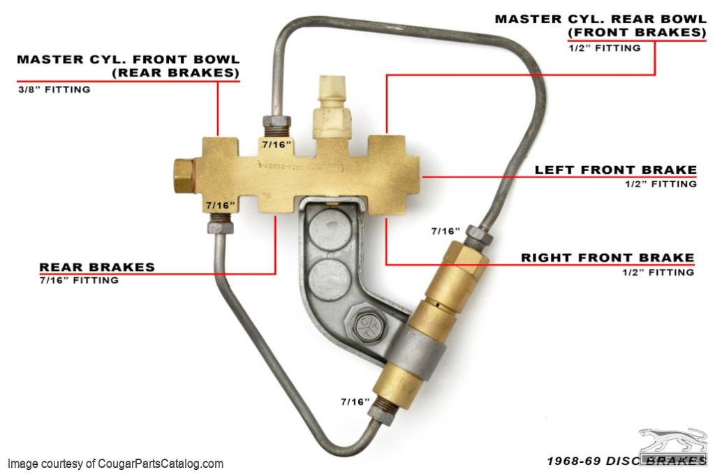
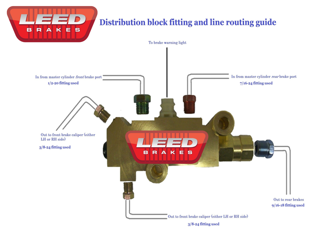
This diagram is the most common way to plumb a pro-portioning valve. In some cases, the right front line will be plugged off at the proportioning valve and the left front line will go to a "T" fitting. From the "T" fitting, the front lines then split off and go to the left and right wheels.

Diagrams Of Brake Proportioning Valve Valve, Diagram, Sensor
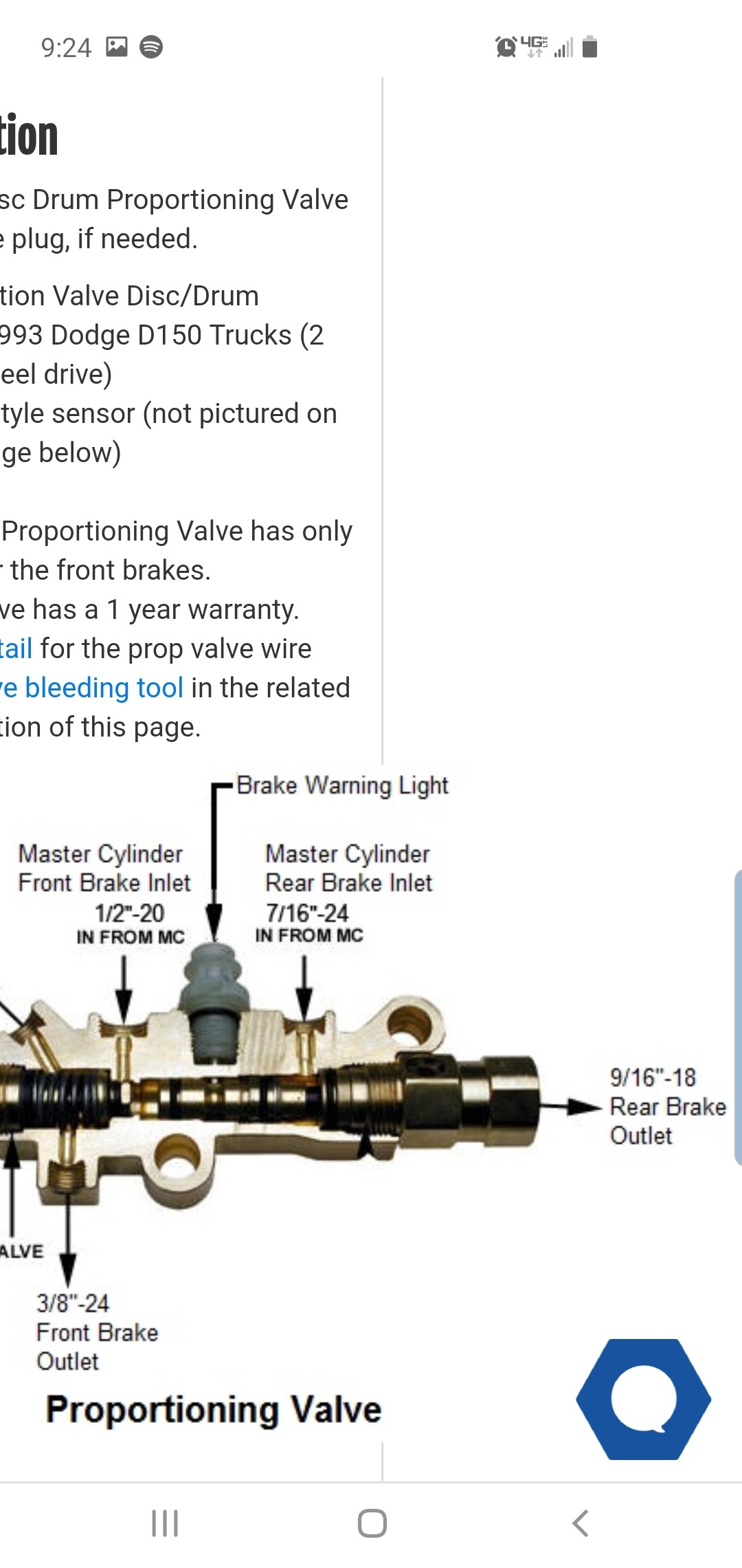
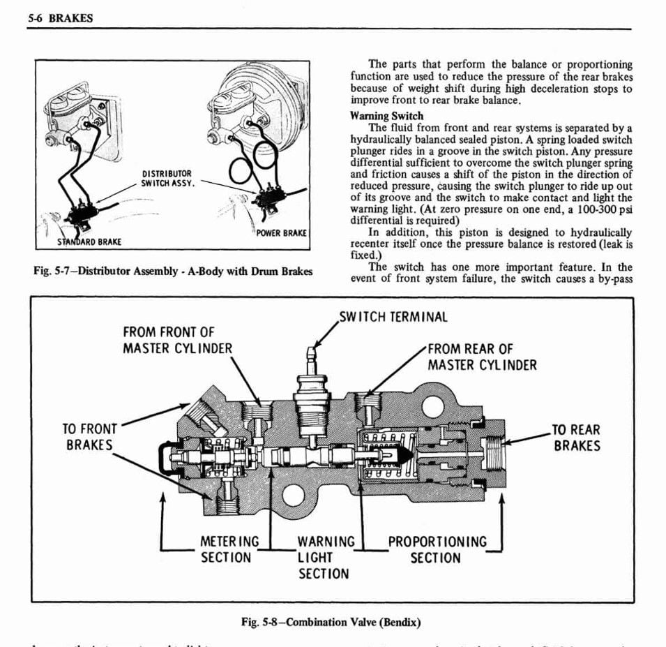
The proportioning valve only lets a certain portion of the pressure through to the rear wheels so that the front wheels apply more braking force. If the proportioning valve were set to 70 percent and the brake pressure were 1,000 pounds per square inch (psi) for the front brakes, the rear brakes would get 700 psi.
Diagrams Of Brake Proportioning Valve My Wiring DIagram
Brake proportioning valve adjustment may seem like a complicated process, but it is quite simple. For all street driven vehicles, the valve will be placed in the rear brake line to reduce the amount of fluid pressure supplied to the rear brakes.. Use our Brake System diagram to help with your street rod brake system project. We also diagram.
Brake Proportioning Valve Diagram Visual Diagram
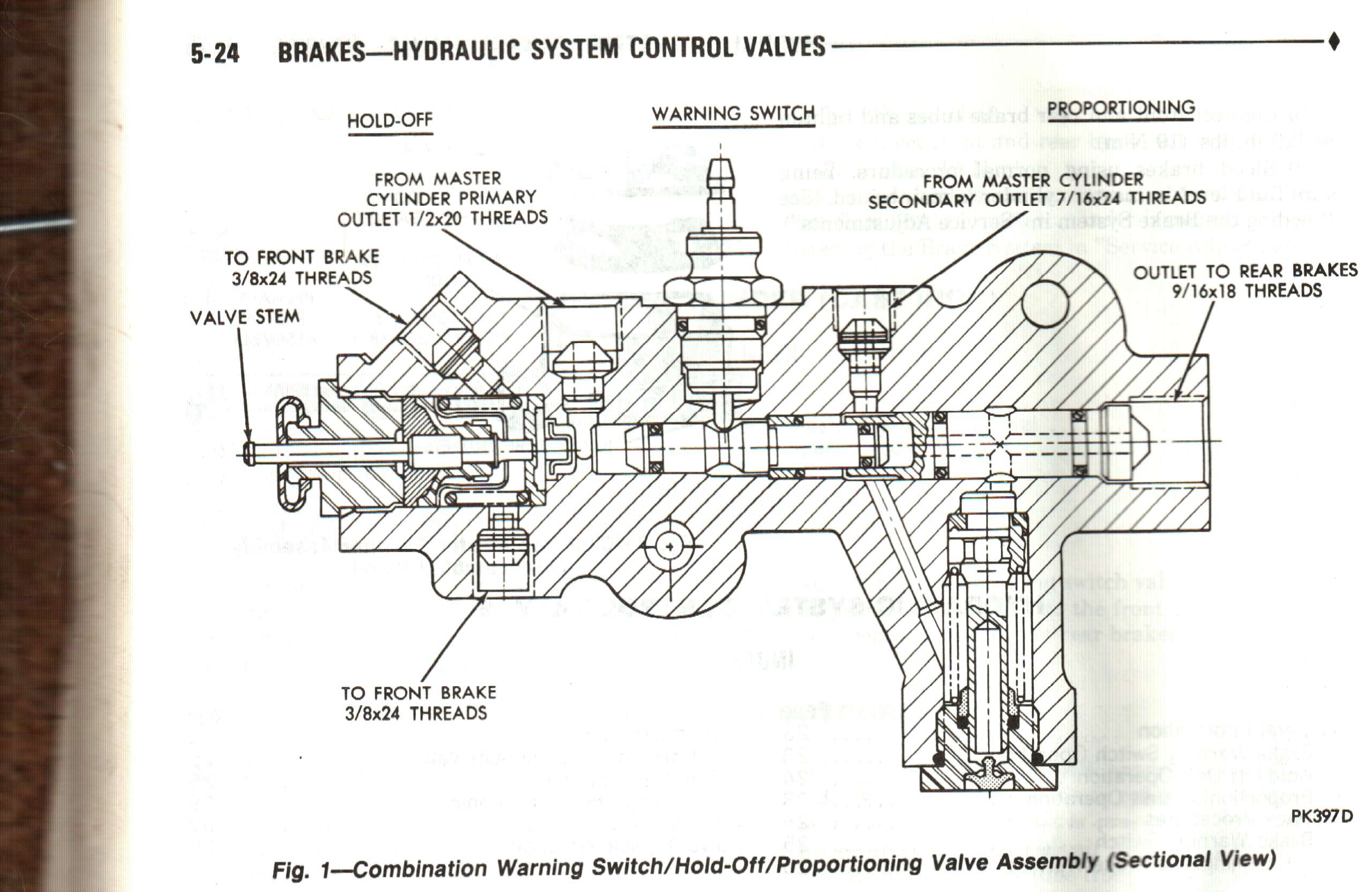
Conventional proportioning valves should really be referred to as "braking force regulators" or "brake pressure regulating valves." While their name might imply true proportional control, in reality they provide a combination of the control found in Figures A and B.

Brake Proportioning Valve Diagram alternator
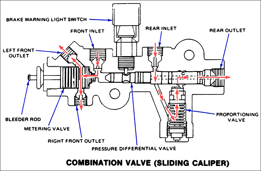
The proportioning valve lets you adjust the rear brake pressure to account for different tires, front to rear weight bias, and the effectiveness of rear disc or drum brakes. How it Works The inner workings of an adjustable proportioning valve are relatively simple but deceptively complex.

Three Function Combination Brake Proportioning Valve PV2
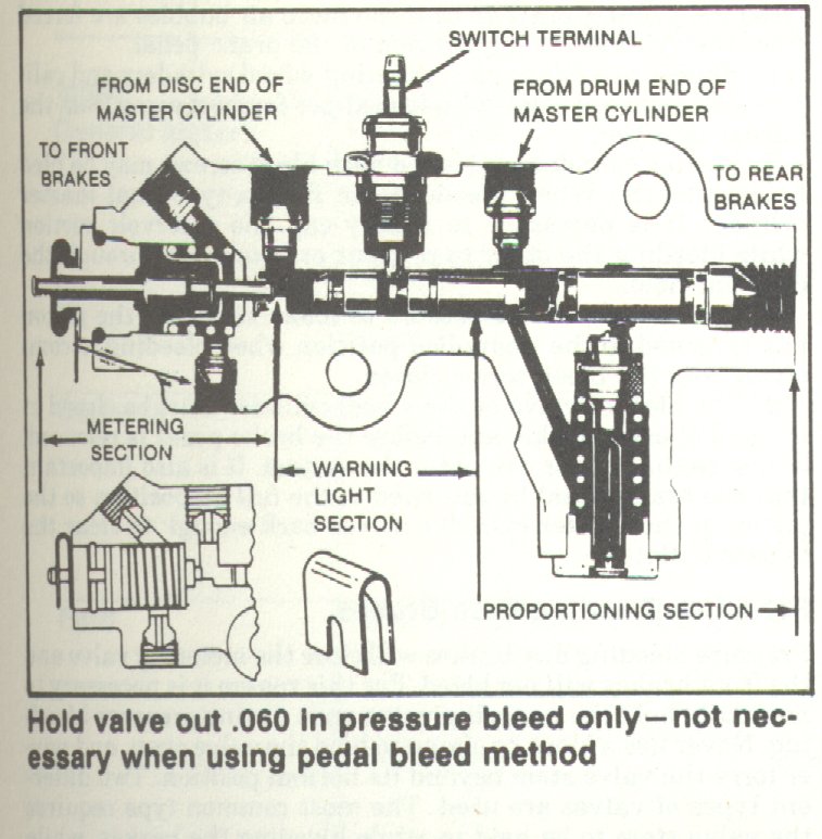
Today in the garage we talk about how a brakes systems proportion valve, hold off valve and combination valves commonly found on classic Camaro, Chevelle, No.
Brake Distribution Block / Proportioning Valve Assembly Disc Power Brake Repro 1968
1) The proportioning valve in the Prop Block will be used to adjust the rear brake pressure of the vehicle.The objective is to balance the pressure of the rear brakes to the front so that under hard braking, the rear brakes do not lock up before the fronts. 2) Start with the valve in the full increase position by turning the knob all the way.

1992 Ford ranger brake proportioning valve
Brake Proportioning Valve Problems - In The Garage with CarParts.com Learn more about the brake proportioning valve and how to check if yours is still working properly with the help of this article.
Proportioning valve replacement
The brake proportioning valve is a special system that is directly attached to the hydraulic fluid that comes from the master cylinder. The main duty of the brake proportioning valve is to separate the hydraulic fluid actually to all the brake calipers at the four wheels.
1976 Ford Brake Switch Diagram Diagram Database
The proportioning valve typically connects the master cylinder to the rest of the braking system, but sometimes it is independent of the cylinder. This valve is necessary for optimizing front-to-rear bias, also referred to as brake balance. It is a spring-loaded component that activates when fluid pressure builds when you step on the brake pedal.

Ford Proportioning Valve Diagram
Read the Chevy High-Peformance technical article on installing and tuning a brake proportioning valve, brought to you by the experts at Chevy High Performance Magazine. Celebrate 75 Years.

Brake proportioning valve
Diagram of master cylinder When the brake pedal is depressed, it pushes on the first (primary piston) through a linkage. The Pressure builds in the cylinder and lines as the brake pedal is depressed further. The pressure between the primary and secondary piston forces the secondary piston to compress the fluid in its circuit.
converting to disc... proportioning valve? manual brakes? Chevelle Tech
PROPORTIONING VALVE DIAGRAM This diagram is the most common way to plumb a proportioning valve. In some cases, the right front line will be plugged off at the proportioning valve and the left front line will go to a "T" fitting. From the "T" fitting, the front lines then split off and go to the left and right wheels.